


At the following you will find the explanation of the components of an calibration certificate for force gauges.
Depending on the force gauge and calibration bearing the content may diversify.
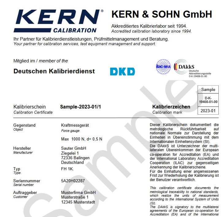
1. "Official" document
The KERN DAkkS calibration laboratory (D-K-19408-01-00) is accredited through the accreditation Point of the German calibration service. The DAkkS calibration certificate is recognised internationally and is available in several languages.
2. Item to be calibrated
The calibration item as well as the type or model with serial number is documented. This means that there is no confusion and guarantees the assignment of the DAkkS calibration certificate to a specific balance.
3. Traceability
The reference standards of the accredited laboratory are monitored in strictly defined cycles and periodically brought into line with national and thereby international standards. This is carefully documented and given on the DAkkS calibration certificate. In this way the basic fundamental traceability to the national standard is ensured.
4. Contracting authority
On the very first page of the DAkkS calibration certificate you will clearly see the applicant or operator of the calibrated checking equipment.
5. Stamp and signature
According to DIN EN ISO 17025, only the designation of the person responsible for the release of the report is required. Due to the value, we additionally print the laboratory stamp as well as the name and signature of the laboratory management and the person responsible for the release of the report.
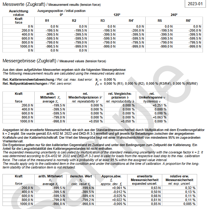
6. Measurands
In this part of the certificate for every direction of force the "rough" measurands of the calibration will be documented for traceability. Depending on precognition of the measuring device, e.g. its type and of course the customer's desires, different calibration processes according to DKD-R 3-3 can be applied. The calibration processes vary in amount and sort of the processed test series (especially in mounting position and rising resp. descending load) and allow to adept the complexity to the customers requirements of accuracy.
Using the example calibration process A is shown. First the force gauge will be loaded three times with preload at calibration maximum load. Then 6 test series within 3 different mounting positions will be assimilated:
- Loading done twice with increasing load (test series R1, R2') within mounting position 0° (generally not exactly defined Arrangement)
- Rotation of the device (to 120°), preload, loading with increasing and decreasing load (test series R3, R4')
- Rotation of the device (to 240°), preload, loading with increasing and decreasing load (test series R5, R6')
Because of the loading done twice with as identical as possible conditions the repeatability can be determined.
The rotation - and for this reason necessary anewed mounting into the loading mechanism - allows conclusion to model and device significiant incertitude at the initiation of calibration force of the device and whose sensibility on it (reproducibility)
The influence of hysteresis of the measuring system on the shown measurand appears by decreasing load at test series R4' and R6'. The mechanical load (distortion, warping) as well as the creep by e.g. thermal effects result that the measurand differes at unloading and loading despite identical calibration force (hysteresis error).
Especially the return to zero therefore is a dimension for the creep of the measuring device while loading.
7. Measuring results
Out of the "rough" measurands the relative technical measurement parameters of the calibrated force gauge can be calculated. At the following the imprinted values within this section of the calibration certificate will be stated, the calculation itself is specified exactly at the calibration norm DKD-R 3-3.
- arithmetic average: the average of the about zero indication corrected displayed values at a loading increment across all test series. It is the best estimated value for the display of the measuring device at the current applied force.
- rel. repeatability b': dimension for the dispersion of the displayed value at identical conditions.
- rel. reproducibility b: dimension for the dispersion of the displayed value at different mounting positions.
- rel. hysteresis error v: dimension for the hysteresis (and drift) at the displayed value at decreasing load.
- rel. deviation of calibration terminal value: comparison of the display at immediate load (at the preload) and "slow" load with calibration maximum load (at test series R1)
- rel. deviation of zero-point: comparison of the display before load and after complete unload, dimension fot the drift during load.
- Y3: by a third-degree polynomial approximated display value of the current development.
- approx. dev. fc: The rel. deviation of this approximation of the actual display value.
- exp. measuring uncertainty: the expanded measuring uncertainty of the determined deviation
- rel. exp. measuring uncertainty: the expanded measuring uncertainty relative to the applied force.
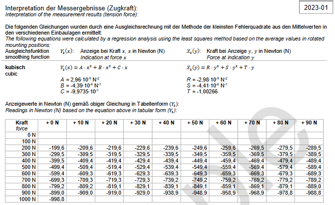
7. Interpretation of the measuring results
The measurement and measuring results mentioned on the preceded page document the indication error of the measuring device at the respectively applied calibration force. There is made no statement for the whole measuring range.
An adjustment theory about the medium display values in the post-assembly positions allow to estimate the indication error of the device over the whole measuring range at optional load. The result of this adjustment theory (with a polynomial of third class under application of the "least squares" method) can be found on page 4 of the calibration certificate.
- indication Y at force x (Y3):
If force x is applied, the force gauge should Show indication Y3(x).
The table represents these theoretical display values at a multiplicity of applied force.
A. B and C therefore are coefficients of the polynomial. - indication X at force y (X3):
If the force gauge shows the value y, it should be the actual applied force X3(y).
R, S and T therefore are coefficients of the polynominal.